Produkt ähnlich wie:
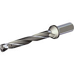
TOP DRILL™ Modular X • 8 x D • Side Lock Shank • Inch
TDMX • 8 x D • Side Lock Shank • Inch
Material Nummer6572259
ISO Katalog NummerTDMX1103R8SL125ASI Katalog NummerTDMX1103R8SL125
- P Stahl
- M Rostfreier Stahl
- K Gusseisen
- N NE-Metalle
- S Hochwarmfeste Legierungen
- .caption
Zylinderschaft – mit Spannfläche
Drilling
Drilling: Inclined Entry
Drilling: Inclined Exit
Drilling: Stacked Plates
Through Coolant: Radial: Drilling
38513
Drilling: Cross-Hole Drilling
Sending to {{cadTool}} in progress...
Downloaded file will be available after import in the {{cadTool}} tool library.
- Überblick
- Anwendungsdaten
- Herunterladen
- Kompatible Teile Maschinenseite
- Kompatible Teile Werkstückseite
- Ersatzteile
- Bewertung
- F&A
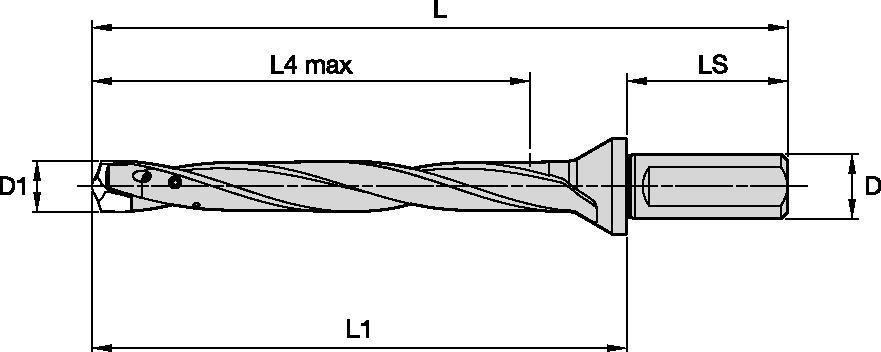
| Material Nummer | 6572259 |
| ISO Katalog Nummer | TDMX1103R8SL125 |
| ASI Katalog Nummer | TDMX1103R8SL125 |
| [SSC] Wendeschneidplatten-Sitz-Größe | M |
| [D1] Bohrerdurchmesser M | 28 mm |
| [D1] Bohrerdurchmesser M | 1.1024 in |
| [D1MAX] Bohrerdurchmesser max. | 28.999 mm |
| [D1MAX] Bohrerdurchmesser max. | 1.1417 in |
| [LS] Schaftlänge | 60 mm |
| [LS] Schaftlänge | 2.3622 in |
| [D] Adapter/Schaft/Bohrungsdurchmesser | 31.75 mm |
| [D] Adapter/Schaft/Bohrungsdurchmesser | 1.25 in |
| [L] Gesamtlänge | 340 mm |
| [L] Gesamtlänge | 13.3859 in |
| [L1] Messlänge der Wendeschneidplatte | 280 mm |
| [L1] Messlänge der Wendeschneidplatte | 11.0237 in |
| [L4] Maximale Bohrtiefe | 232 mm |
| [L4] Maximale Bohrtiefe | 9.1339 in |
Werkstoffe
- Stahl
- Rostfreier Stahl
- Gusseisen
- NE-Metalle
- Hochwarmfeste Legierungen
- .caption
Uses and application
Zylinderschaft – mit Spannfläche
Drilling
Drilling: Inclined Entry
Drilling: Inclined Exit
Drilling: Stacked Plates
Through Coolant: Radial: Drilling
38513
Drilling: Cross-Hole Drilling
Features and benefits
- Flanged shank with a single flat for maximum rigidity
- Internal coolant channels
- Front clamping. No needs to disassemble the body from the tool holder to change the insert
- Highly engineered pocket seat design for high stability even in critical operations
Lösung erstellen, um Vorschübe und Geschwindigkeiten zu berechnen
Nachdem Sie eine Lösung erstellt haben, wählen Sie einfach das Symbol für Vorschübe und Geschwindigkeiten und unser System gibt Ihnen Empfehlungen. Sie können die Informationen anpassen, indem Sie Ihre Maschine und Spezifikationen hinzufügen oder Anpassungen mithilfe der Schieberegler vornehmen.
Anwendungsdaten
 |  |  | ||||||||
| Schnittgeschwindigkeit | ||||||||||
| Bereich | Empfohlene Vorschubrate (f) pro Umdrehung | |||||||||
| Werkstoffgruppe | Min. | Startwert | Max. | Werkzeugdurchmesser | 16,0 | 20,0 | 25,0 | 32,0 | 40,0 | |
| P | 1 | 90 | 125 | 170 | mm/U | 0,19–0,45 | 0,25–0,48 | 0,25–0,52 | 0,28–0,57 | 0,29–0,60 |
| 2 | 105 | 140 | 180 | mm/U | 0,23–0,46 | 0,28–0,50 | 0,30–0,52 | 0,33–0,57 | 0,35–0,60 | |
| 3 | 50 | 75 | 100 | mm/U | 0,23–0,46 | 0,28–0,50 | 0,30–0,52 | 0,33–0,57 | 0,35–0,60 | |
| 4 | 50 | 75 | 100 | mm/U | 0,19–0,45 | 0,22–0,48 | 0,25–0,50 | 0,28–0,55 | 0,29–0,58 | |
| 5 | 50 | 65 | 80 | mm/U | 0,16–0,32 | 0,18–0,36 | 0,22–0,42 | 0,24–0,46 | 0,25–0,48 | |
| 6 | 50 | 65 | 80 | mm/U | 0,16–0,32 | 0,18–0,36 | 0,22–0,42 | 0,24–0,46 | 0,25–0,48 | |
| M | 1 | 40 | 80 | 110 | mm/U | 0,11–0,26 | 0,13–0,28 | 0,13–0,32 | 0,14–0,35 | 0,15–0,37 |
| 2 | 35 | 55 | 75 | mm/U | 0,11–0,26 | 0,13–0,28 | 0,13–0,32 | 0,14–0,35 | 0,15–0,37 | |
| 3 | 20 | 35 | 50 | mm/U | 0,11–0,26 | 0,13–0,28 | 0,13–0,32 | 0,14–0,35 | 0,15–0,37 | |
| K | 1 | 60 | 95 | 170 | mm/U | 0,25–0,48 | 0,28–0,52 | 0,32–0,56 | 0,35–0,62 | 0,37–0,65 |
| 2 | 60 | 75 | 90 | mm/U | 0,25–0,48 | 0,28–0,52 | 0,32–0,56 | 0,35–0,62 | 0,37–0,65 | |
| 3 | 40 | 65 | 90 | mm/U | 0,21–0,44 | 0,23–0,48 | 0,25–0,50 | 0,28–0,55 | 0,29–0,58 | |
Anwendungsdaten • MS(M) • WM15PD • Metrisch
| Werkstoffgruppe |  |  | ||||||||
| Schnittgeschwindigkeit | ||||||||||
| Bereich | Empfohlene Vorschubrate (f) pro Umdrehung | |||||||||
| – | – | Min. | Startwert | Max. | Werkzeugdurchmesser | 16,0 | 20,0 | 25,0 | 32,0 | 40,0 |
| M | 1 | 40 | 80 | 110 | mm/U | 0,11 – 0,26 | 0,13 – 0,28 | 0,13 – 0,32 | 0,14 – 0,35 | 0,15 – 0,37 |
| 2 | 35 | 55 | 75 | mm/U | 0,11 – 0,26 | 0,13 – 0,28 | 0,13 – 0,32 | 0,14 – 0,35 | 0,15 – 0,37 | |
| 3 | 20 | 35 | 50 | mm/U | 0,11 – 0,26 | 0,13 – 0,28 | 0,13 – 0,32 | 0,14 – 0,35 | 0,15 – 0,37 | |
| K | 1 | 90 | 135 | 175 | mm/U | 0,19 – 0,25 | 0,22 – 0,29 | 0,29 – 0,38 | 0,32 – 0,43 | 0,33 – 0,50 |
| 2 | 80 | 120 | 140 | mm/U | 0,19 – 0,25 | 0,22 – 0,29 | 0,29 – 0,38 | 0,32 – 0,43 | 0,33 – 0,50 | |
| 3 | 70 | 110 | 125 | mm/U | 0,18 – 0,26 | 0,21 – 0,29 | 0,23 – 0,37 | 0,25 – 0,42 | 0,27 – 0,46 | |
| N | 1 | 90 | 155 | 220 | mm/U | 0,25 – 0,50 | 0,28 – 0,56 | 0,32 – 0,63 | 0,32 – 0,70 | 0,32 – 0,70 |
| 2 | 90 | 155 | 220 | mm/U | 0,25 – 0,50 | 0,28 – 0,56 | 0,32 – 0,63 | 0,32 – 0,70 | 0,32 – 0,70 | |
| 3 | 80 | 120 | 160 | mm/U | 0,25 – 0,50 | 0,28 – 0,56 | 0,32 – 0,63 | 0,32 – 0,70 | 0,32 – 0,70 | |
| 4 | 90 | 155 | 220 | mm/U | 0,25 – 0,50 | 0,28 – 0,56 | 0,32 – 0,63 | 0,32 – 0,70 | 0,32 – 0,70 | |
| 5 | 160 | 200 | 240 | mm/U | 0,25 – 0,50 | 0,28 – 0,56 | 0,32 – 0,63 | 0,32 – 0,70 | 0,32 – 0,70 | |
| 6 | 160 | 200 | 240 | mm/U | 0,25 – 0,50 | 0,28 – 0,56 | 0,32 – 0,63 | 0,32 – 0,70 | 0,32 – 0,70 | |
| S | 1 | 20 | 40 | 60 | mm/U | 0,07 – 0,12 | 0,09 – 0,14 | 0,11 – 0,17 | 0,13 – 0,20 | 0,16 – 0,25 |
| 2 | 15 | 30 | 45 | mm/U | 0,07 – 0,12 | 0,09 – 0,14 | 0,11 – 0,17 | 0,13 – 0,20 | 0,16 – 0,25 | |
| 3 | 15 | 30 | 45 | mm/U | 0,07 – 0,12 | 0,09 – 0,14 | 0,11 – 0,17 | 0,13 – 0,20 | 0,16 – 0,25 | |
| 4 | 10 | 25 | 40 | mm/U | 0,07 – 0,12 | 0,13 – 0,20 | 0,16 – 0,25 | 0,18 – 0,28 | 0,21 – 0,31 | |
Application Data • MS(M) • WM15PD • Inch
 |  | |||||||||
| Schnittgeschwindigkeit | ||||||||||
| Bereich | Empfohlene Vorschubrate (f) pro Umdrehung | |||||||||
| Werkstoffgruppe | – | Min. | Startwert | Max. | Werkzeugdurchmesser | 0.630 | 0.787 | 1.000 | 1.260 | 1.575 |
| M | 1 | 131 | 262 | 361 | IPR | .004 – .010 | .005 – .012 | .005 – .013 | .006 – .014 | .006 – .015 |
| 2 | 115 | 180 | 246 | IPR | .004 – .010 | .005 – .012 | .005 – .013 | .006 – .014 | .006 – .015 | |
| 3 | 66 | 115 | 164 | IPR | .004 – .010 | .005 – .012 | .005 – .013 | .006 – .014 | .006 – .015 | |
| K | 1 | 295 | 443 | 574 | IPR | .007 – .010 | .009 – .019 | .011 – .015 | .013 – .017 | .013 – .020 |
| 2 | 262 | 394 | 459 | IPR | .007 – .010 | .009 – .019 | .011 – .015 | .013 – .017 | .013 – .020 | |
| 3 | 230 | 361 | 410 | IPR | .007 – .010 | .009 – .019 | .009 – .015 | .010 – .017 | .011 – .020 | |
| N | 1 | 295 | 508 | 722 | IPR | .010 – .020 | .011 – .022 | .013 – .025 | .013 – .028 | .013 – .028 |
| 2 | 295 | 508 | 722 | IPR | .010 – .020 | .011 – .022 | .013 – .025 | .013 – .028 | .013 – .028 | |
| 3 | 262 | 394 | 525 | IPR | .010 – .020 | .011 – .022 | .013 – .025 | .013 – .028 | .013 – .028 | |
| 4 | 295 | 508 | 722 | IPR | .010 – .020 | .011 – .022 | .013 – .025 | .013 – .028 | .013 – .028 | |
| 5 | 525 | 656 | 787 | IPR | .010 – .020 | .011 – .022 | .013 – .025 | .013 – .028 | .013 – .028 | |
| 6 | 525 | 656 | 787 | IPR | .010 – .020 | .011 – .022 | .013 – .025 | .013 – .028 | .013 – .028 | |
| S | 1 | 66 | 131 | 197 | IPR | .003 – .005 | .004 – .006 | .004 – .007 | .005 – .008 | .006 – .010 |
| 2 | 49 | 98 | 148 | IPR | .003 – .005 | .004 – .006 | .004 – .007 | .005 – .008 | .006 – .010 | |
| 3 | 49 | 98 | 148 | IPR | .003 – .005 | .004 – .006 | .004 – .007 | .005 – .008 | .006 – .010 | |
| 4 | 33 | 82 | 131 | IPR | .003 – .005 | .005 – .008 | .006 – .010 | .007 – .011 | .008 – .012 | |
Toleranz
| Metrisch | ||
| Toleranz | ||
| Wendeschneidplatte | TDMX….PK; MS; FP | TDMX…FPE |
| D1 | Toleranz k7 | Toleranz s7 |
| 16-18 | .+0,001/+0.019 | .+0.028/+0.046 |
| >18-30 | .+0,002/+0,023 | .+0,035/+0,056 |
| >30-40 | .+0,002/+0,027 | .+0,043/+0,068 |
| Zoll | ||
| Toleranz | ||
| Wendeschneidplatte | TDMX….PK | |
I have read and accepted the Terms & Conditions of use
CAD Drawings Models
Can’t find the file type you’re looking for?
Product data

