VariMill™ Chip Splitters
High-Performance Solid Carbide End Mills
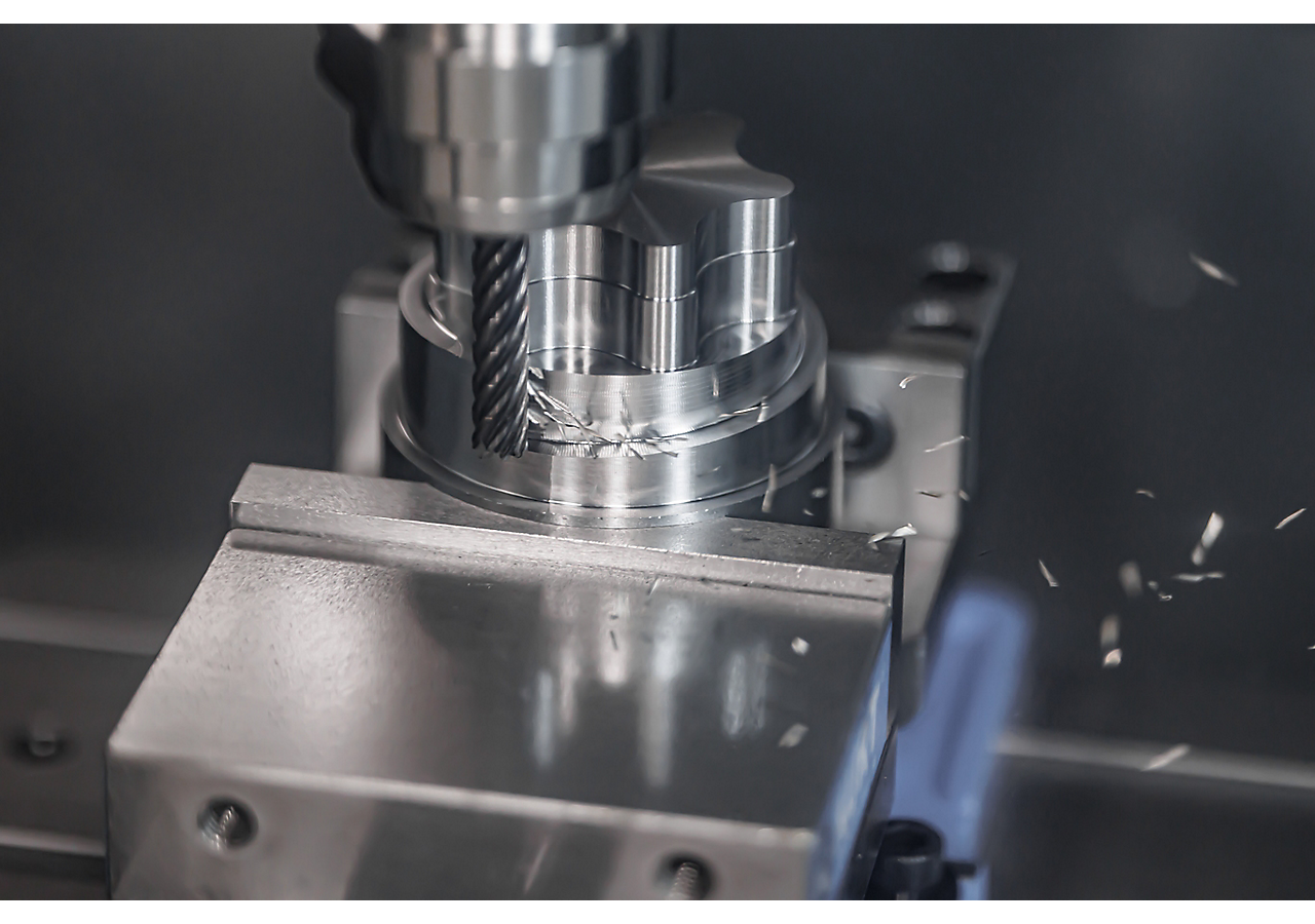
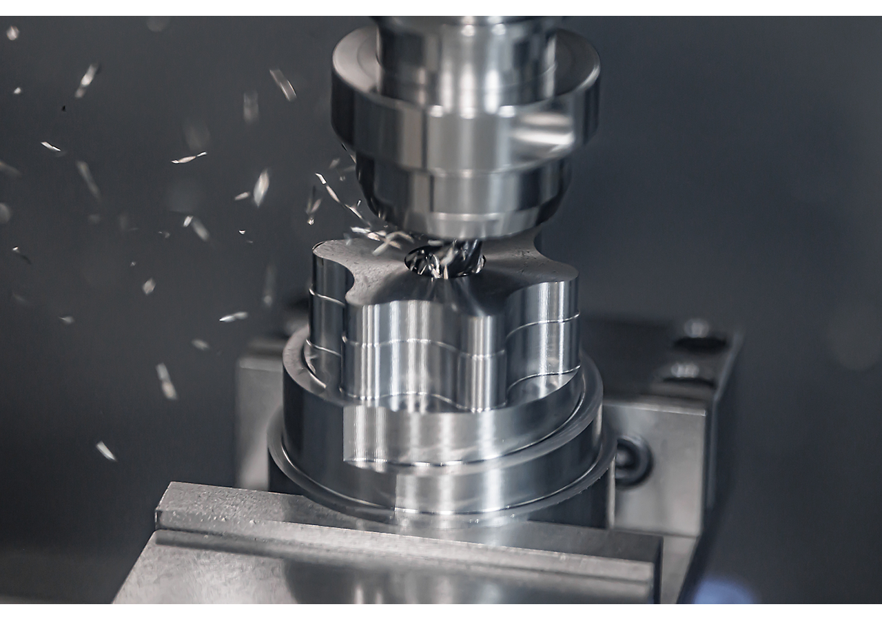
The VariMill Chip Splitters series of end mills delivers excellent chip control allowing the tool to run in longer axial depth of cuts while productively diving into deep pockets in steel, stainless steel and high-temp alloy applications.
The end mill is available in 5- and 7-flute configurations, both of which feature unequal flute spacing for vibration dampening.
The end mill’s key design features are small gashes (chip splitters) along the cutting edge to break the chip into shorter sections without reducing the wall finish. These short chips are easier to evacuate from the cutting area, especially when machining deep cavities. The chip splitter feature can also prevent bird nesting and lessen the potential for tool breakage.
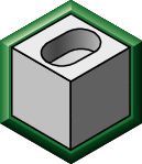 Pocket (25)
 Pocket Helical (25)
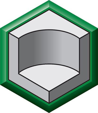 Pocket Milling (25)
 Shoulder Milling (61)Shoulder Roughing (38)Shoulder Square End (25)
 Trochoidal Milling (25)
ISO Catalog Number
ANSI Catalog Number
to find similar products.Please select a file to download
Models
. Please enter the desired qty for the material(s) you want to include in your promotion or Proceed Without Promotion and only your base materials will be added to the cart.
Minimum quantity should be
| SAP Material Number | ISO Catalog Number | Grade |
|---|
You are about to leave the Solution building process.
Are you sure you want to leave?