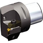
Cutting Units • Top Thread™ and Top Groove™

NR 45°

Cutting Units • Top Thread™ and Top Groove™

使用法と用途

  • Shank - PSCShank - PSC
  • メーカー仕様:ISO 26623メーカー仕様:ISO 26623
  • Coolant: Through Coolant 80 bar MaximumCoolant: Through Coolant 80 bar Maximum
  • Coolant: Through Coolant 1200 psi MaximumCoolant: Through Coolant 1200 psi Maximum
フィルタを選択
Filters
フィルタ表示
メートル
インチ
keyFilters
Workpiece Material
Workpiece Material
  • P Steel (2)
    • P0
      Low-Carbon Steels, Long Chipping C < .25%; <125 HB; <530 N/mm^2 UTS (2)
    • P1
      Low-Carbon Steels, Short Chipping C < .25%; <125 HB; <530 N/mm^2 UTS (2)
    • P2
      Medium and High Carbon Steels C < .25%; <220 HB; <25 HRC; >530 N/mm^2 UTS (2)
    • P3
      Alloy Steels & Tool Steels C > .25%; <330 HB; <35 HRC; 600-850 N/mm^2 UTS (2)
    • P4
      Alloy Steels & Tool Steels C > .25%; 350-420 HB; 35-43 HRC; 850-1400 N/mm^2 UTS (2)
    • P5
      Ferritic, Martensitic, and PH Stainless Steels <330 HB; <35 HRC; 600-900 N/mm^2 UTS (2)
    • P6
      High Strength Ferritic, Martensitic, and PH Stainless Steels 350-450 HB; 35-43 HRC; 900-2400 N/mm^2 UTS (2)
  • M Stainless Steel (2)
    • M1
      Austenitic Stainless Steel 130-200 HB; <600 N/mm^2 UTS (2)
    • M2
      High Strength Austenitic Stainless and Cast Stainless Steels 150-230 HB; <25 HRC; >600 N/mm^2 UTS (2)
    • M3
      Duplex Stainless Steel 135-275 HB; <30 HRC; 500-1200 N/mm^2 UTS (2)
  • K Cast Iron (2)
    • K1
      Gray Cast Iron 120-290 HB; <32 HRC; 125-500 N/mm^2 UTS (2)
    • K2
      Low and Medium Strength CGI and Ductile Irons 130-260 HB; <28 HRC; <600 N/mm^2 UTS (2)
    • K3
      High Strength Ductile and Austempered Ductile Iron 180-350 HB; <43 HRC; >600 N/mm^2 UTS (2)
  • N Non-Ferrous Materials (2)
    • N1
      Wrought Aluminum (2)
    • N2
      Low-Silicon Aluminum Alloys and Magnesium Alloys Si <12.2% (2)
    • N3
      High-Silicon Aluminum Alloys Si >12.2% (2)
    • N4
      Copper, Brass, Zinc-based on machinability index range of 70-100 (2)
    • N5
      Nylon, Plastics, Rubbers, Phenolics, Resins, Fiberglass (2)
    • N6
      Carbon, Graphite Composites, CFRP (2)
    • N7
      MMC's (2)
  • S High-Temp Alloys (2)
    • S1
      Iron-Based, Heat-Resistant Alloys 160-260 HB; 25-48 HRC; 500-1200 N/mm^2 UTS (2)
    • S2
      Cobalt-Based, Heat-Resistant Alloys 250-450 HB; 25-48 HRC; 1000-1450 N/mm^2 UTS (2)
    • S3
      Nickel-Based, Heat Resistant Alloys 160-450 HB; <48 HRC; 600-1700 N/mm^2 UTS (2)
    • S4
      Titanium and Titanium Alloys 300-400 HB; 33-43 HRC; 900-1600 N/mm^2 UTS (2)
  • H Hardened Materials (2)
    • H1
      Hardened Materials 44-48 HRC (2)
    • H2
      Hardened Materials 48-55 HRC (2)
    • H3
      Hardened Materials 56-60 HRC (2)
    • H4
      Hardened Materials >60 HRC (2)
Applications
Applications
  • Grooving Grooving (2)
  • ID Grooving ID Grooving (2)
Type of Thread
Type of Thread
  • 60 (2)
  • ACME (2)
  • API (2)
  • API RD (2)
  • BSW (2)
  • BUTTRESS (2)
  • M (2)
  • NPT (2)
  • STUB ACME (2)
  • UN (2)
  • UNJ (2)
Cutting Condition
Cutting Condition
  • Heavily Interrupted Cut (2)
  • Lightly Interrupted Cut (2)
  • Smooth Cut (2)
  • Varying Depth of Cut (2)
Cutting Edges Per Insert
  • 1.0 (2)
  • 2.0 (2)
Cutting Edges Per Insert Min to Cutting Edges Per Insert Max
cornerConfiguration
Corner Radius
Corner Radius
  • 0.002 in (2)
  • 0.003 in (2)
  • 0.004 in (2)
  • 0.005 in (2)
  • 0.006 in (2)
  • 0.007 in (2)
  • 0.008 in (2)
  • 0.01 in (2)
  • 0.011 in (2)
  • 0.012 in (2)
  • 0.014 in (2)
  • 0.016 in (2)
  • 0.017 in (2)
  • 0.019 in (2)
  • 0.02 in (2)
  • 0.023 in (2)
  • 0.031 in (2)
  • 0.035 in (2)
  • 0.039 in (2)
  • 0.047 in (2)
  • 0.049 in (2)
  • 0.06 in (2)
  • 0.062 in (2)
  • 0.063 in (2)
  • 0.069 in (2)
  • 0.078 in (2)
  • 0.079 in (2)
  • 0.089 in (2)
  • 0.095 in (2)
Corner Radius Min to Corner Radius Max
Corner Radius
Corner Radius
  • 0.05 mm (2)
  • 0.076 mm (2)
  • 0.1 mm (2)
  • 0.125 mm (2)
  • 0.151 mm (2)
  • 0.176 mm (2)
  • 0.2 mm (2)
  • 0.225 mm (2)
  • 0.25 mm (2)
  • 0.275 mm (2)
  • 0.301 mm (2)
  • 0.325 mm (2)
  • 0.351 mm (2)
  • 0.4 mm (2)
  • 0.426 mm (2)
  • 0.45 mm (2)
  • 0.476 mm (1)
  • 0.5 mm (2)
  • 0.576 mm (2)
  • 0.775 mm (2)
  • 0.9 mm (2)
  • 1.0 mm (2)
  • 1.201 mm (2)
  • 1.25 mm (2)
  • 1.5 mm (2)
  • 1.576 mm (2)
  • 1.6 mm (2)
  • 1.75 mm (2)
  • 1.975 mm (2)
  • 2.0 mm (2)
  • 2.25 mm (2)
  • 2.401 mm (2)
Corner Radius Min to Corner Radius Max
application
Minimum Depth of Cut
Minimum Feed
Minimum Feed
Grade Of Cutting Tool
  • K2885 (2)
  • K313 (2)
  • K420 (2)
  • K4H (2)
  • K68 (2)
  • KB1345 (2)
  • KB1630 (2)
  • KB5625 (2)
  • KBH20 (1)
  • KC250 (2)
  • KC5010 (2)
  • KC5025 (2)
  • KC5410 (2)
  • KC710 (2)
  • KC720 (2)
  • KC722 (2)
  • KC730 (2)
  • KC732 (2)
  • KC810 (2)
  • KC850 (2)
  • KC910 (2)
  • KC9110 (2)
  • KC9120 (2)
  • KC9320 (2)
  • KC935 (2)
  • KC950 (2)
  • KCK20 (2)
  • KCK20B (2)
  • KCP10B (2)
  • KCP25B (2)
  • KCU10 (2)
  • KCU25 (2)
  • KD050 (1)
  • KD081 (2)
  • KD100 (2)
  • KD120 (2)
  • KD1425 (2)
  • KT175 (2)
  • KT315 (2)
  • KU10T (2)
  • KU25T (2)
  • KU30T (2)
  • KY3000 (2)
  • THM (2)
  • TN10P (2)
  • TN6010 (2)
  • TN6025 (2)
  • TN7110 (2)
  • WU10HT (1)
  • WU25PT (1)
frontEnd
Cutting Width
Cutting Width
  • 0.039 in (2)
  • 0.047 in (2)
  • 0.06 in (2)
  • 0.062 in (2)
  • 0.069 in (2)
  • 0.073 in (2)
  • 0.078 in (2)
  • 0.079 in (2)
  • 0.088 in (2)
  • 0.089 in (1)
  • 0.094 in (1)
  • 0.095 in (2)
  • 0.097 in (2)
  • 0.098 in (2)
  • 0.105 in (2)
  • 0.108 in (2)
  • 0.11 in (2)
  • 0.119 in (2)
  • 0.122 in (2)
  • 0.125 in (2)
  • 0.126 in (2)
  • 0.128 in (2)
  • 0.131 in (1)
  • 0.138 in (2)
  • 0.143 in (2)
  • 0.156 in (2)
  • 0.157 in (2)
  • 0.167 in (2)
  • 0.169 in (2)
  • 0.177 in (2)
  • 0.178 in (2)
  • 0.185 in (2)
  • 0.188 in (2)
  • 0.189 in (2)
  • 0.192 in (1)
  • 0.193 in (1)
  • 0.195 in (2)
Cutting Width Min to Cutting Width Max
Cutting Width
Cutting Width
  • 1.0 mm (2)
  • 1.201 mm (2)
  • 1.5 mm (2)
  • 1.576 mm (2)
  • 1.75 mm (2)
  • 1.826 mm (2)
  • 1.975 mm (2)
  • 2.0 mm (2)
  • 2.2 mm (2)
  • 2.225 mm (2)
  • 2.25 mm (1)
  • 2.375 mm (1)
  • 2.401 mm (2)
  • 2.475 mm (2)
  • 2.5 mm (2)
  • 2.676 mm (2)
  • 2.75 mm (2)
  • 2.801 mm (2)
  • 3.0 mm (2)
  • 3.1 mm (2)
  • 3.176 mm (2)
  • 3.2 mm (2)
  • 3.25 mm (2)
  • 3.325 mm (1)
  • 3.5 mm (2)
  • 3.6 mm (2)
  • 3.95 mm (2)
  • 3.975 mm (1)
  • 4.0 mm (2)
  • 4.25 mm (2)
  • 4.3 mm (2)
  • 4.5 mm (2)
  • 4.525 mm (2)
  • 4.7 mm (2)
  • 4.775 mm (2)
  • 4.801 mm (2)
  • 4.875 mm (1)
  • 4.9 mm (1)
  • 4.95 mm (2)
Cutting Width Min to Cutting Width Max
insertGeometry
Cutting Tool Material
  • B H (2)
  • B L (2)
  • C N (2)
  • D P (2)
  • H T (2)
  • H W (2)
No filters matching ""
以下に示すパラメータのいずれかを使用して表示列を変更することができます。最大7列まで表示できます。
表示 1- 2 / 2 結果
列を選択
フィルタを選択
メートル
インチ
表示
メートル
インチ
SAP Material Number ISO Catalog Number ANSI Catalog Number [F] F Dimension [F] F Dimension Gage Insert Weight Kilograms [L1] Tool Length [L1] Tool Length [DM] Minimum Bore Diameter [DM] Minimum Bore Diameter
6338311 PSC50NRL3 PSC50NRL3 35 1.378 NU3R 0.69 52 2.047 64 2.519
    定価:
    $471.17 /各
    価格::
    数量
    6338312 PSC50NRR3 PSC50NRR3 35 1.378 NU3L 0.69 52 2.047 64 2.519
      定価:
      $471.94 /各
      価格::
      数量
      定価:
      割引: %
      価格::
      配置転換 この品目はありません
      交換品 この品目は、代理店経由で入手できる場合があります
      数量

      販売包装単位

      product-image
      Please adjust the following properties from

      ISO製品型番

      ANSI製品型番

      to find similar products.

      The following files are available

      Please select a file to download

      Models

      Product data

      複製を作成しようとしています . 続行しますか?
      削除しようとしています 続行しますか?
      の名前を何に変更しますか?
      有効な名前を入力してください
      重複の名前を入力してください
      有効な名前を入力してください
      マイソリューションページにを追加しようとしています. 続行しますか?
      有効な名前を入力してください
      次のコピーを送信

      Oops, you have used your own email address! Please enter another email address to proceed.

      An active user does not exist under that email address. Please Click Here , to send a registration invitation to


      有効なメールアドレスを入力してください
      有効な名前を入力してください
      ダッシュボード情報を表示するには、ログインする必要があります
      Session expired due to inactivity, please login again
      カートに追加しようとした製品()はありません カスタマーサービスにお問い合わせください。
      アイテムがカートに正常に追加されました
      カートを表示
      DOWNLOAD TYPE:


      . Please enter the desired qty for the material(s) you want to include in your promotion or Proceed Without Promotion and only your base materials will be added to the cart.

      Minimum quantity should be

      SAP Material Number ISO製品型番 材種    
      Thank you for your registration, pending approval & completion of the registration, your access is currently limited. Full utilization of product search capabilities & collaboration space is available and will remain. Please allow 2 business days for registration completion.

      You are about to leave the Solution building process.

      Are you sure you want to leave?