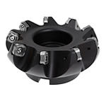
M8065HDを使用すれば、一貫して高い切り屑除去率を維持しながら高い切込み量を適用することによって、鋼および鋳鉄の被削材の重切削ミーリングに容易に対応可能です。

M8065HDにより、すべての工作機械オペレーターは購入時から加工時まで、確実にコストを低減することができます。


特徴と利点

  • WP35CM、WU20PM、WK15CM材種を使用した、汎用性の高いSNMX15 -MM形状インサート。
  • カッターの65°の切込み角と厚さ6.35 mmのインサートの組み合わせ。
  • 高い切込み量(DOC)(最大Ap1は9 mm)。
  • 効率的な切り屑排出を実現する非常に広い切り屑溝設計。
  • ポジのすくい形状を備えたインサート。
  • インサートポケットシートの大きい壁面により、インサートシートの安定性を向上。
  • 右勝手および左勝手のカッターに共通するインサート。
  • より安定したクランプを実現する強力なインサート用ねじ(M4.5)。

1つの形状、3つの材種

最新のVictory™材種WP35CM、WK15CM、およびWU20PMを使用した1つのユニバーサル形状。簡素化により、より多くの被削材を加工可能です。定評のあるVictory™材種はほとんどの対象アプリケーションに対応します。

材種WK15CM - 鋳鉄に最適
乾式加工における一般的なミーリング向けで、バランスの取れた靭性とともに耐磨耗性を備えた材種ですが、湿式加工での使用も可能です。

材種WP35CM - 鋼と鋳鉄に最適
この材種は、一般的なミーリングから粗加工ミーリングまで、幅広いアプリケーションに対応しています。乾式加工で最高のパフォーマンスを発揮しますが、湿式加工でも使用可能です。

材種WU20PM - 鋼、ステンレス鋼、耐熱合金に理想的、ねずみ鋳鉄やノジュラー鋳鉄にも最適
良好な耐欠損性を持つとともに、耐摩耗性の改善と強度の向上が図られています。乾式加工および湿式加工のいずれにも使用可能です。

フィルタを選択
フィルタ
フィルタ表示
メートル
インチ
keyFilters
Workpiece Material
Workpiece Material
  • P Steel (16)
    • P0
      Low-Carbon Steels, Long Chipping C < .25%; <125 HB; <530 N/mm^2 UTS (16)
    • P1
      Low-Carbon Steels, Short Chipping C < .25%; <125 HB; <530 N/mm^2 UTS (16)
    • P2
      Medium and High Carbon Steels C < .25%; <220 HB; <25 HRC; >530 N/mm^2 UTS (16)
    • P3
      Alloy Steels & Tool Steels C > .25%; <330 HB; <35 HRC; 600-850 N/mm^2 UTS (16)
    • P4
      Alloy Steels & Tool Steels C > .25%; 350-420 HB; 35-43 HRC; 850-1400 N/mm^2 UTS (16)
    • P5
      Ferritic, Martensitic, and PH Stainless Steels <330 HB; <35 HRC; 600-900 N/mm^2 UTS (16)
    • P6
      High Strength Ferritic, Martensitic, and PH Stainless Steels 350-450 HB; 35-43 HRC; 900-2400 N/mm^2 UTS (16)
  • M Stainless Steel (16)
    • M1
      Austenitic Stainless Steel 130-200 HB; <600 N/mm^2 UTS (16)
    • M2
      High Strength Austenitic Stainless and Cast Stainless Steels 150-230 HB; <25 HRC; >600 N/mm^2 UTS (16)
    • M3
      Duplex Stainless Steel 135-275 HB; <30 HRC; 500-1200 N/mm^2 UTS (16)
  • K Cast Iron (16)
    • K1
      Gray Cast Iron 120-290 HB; <32 HRC; 125-500 N/mm^2 UTS (16)
    • K2
      Low and Medium Strength CGI and Ductile Irons 130-260 HB; <28 HRC; <600 N/mm^2 UTS (16)
    • K3
      High Strength Ductile and Austempered Ductile Iron 180-350 HB; <43 HRC; >600 N/mm^2 UTS (16)
  • S High-Temp Alloys (16)
    • S4
      Titanium and Titanium Alloys 300-400 HB; 33-43 HRC; 900-1600 N/mm^2 UTS (16)
Select All Star
  • CN (5)
  • DE (10)
  • IN (12)
Applications
Applications
  • Chamfer Milling Chamfer Milling (14)
  • Face Milling Face Milling (14)
Cutting Diameter
Cutting Diameter
  • 1.969 in (1)
  • 2.48 in (1)
  • 3.0 in (1)
  • 3.15 in (1)
  • 3.938 in (1)
  • 4.0 in (1)
  • 4.921 in (1)
  • 5.0 in (1)
  • 6.0 in (1)
  • 6.299 in (1)
  • 7.875 in (1)
  • 8.0 in (1)
  • 9.843 in (1)
  • 12.403 in (1)
Cutting Diameter Min to Cutting Diameter Max
Cutting Diameter
Cutting Diameter
  • 50.0 mm (1)
  • 63.0 mm (1)
  • 76.2 mm (1)
  • 80.0 mm (1)
  • 100.0 mm (1)
  • 101.601 mm (1)
  • 125.0 mm (1)
  • 127.0 mm (1)
  • 152.4 mm (1)
  • 160.0 mm (1)
  • 200.0 mm (1)
  • 203.201 mm (1)
  • 250.0 mm (1)
  • 315.0 mm (1)
Cutting Diameter Min to Cutting Diameter Max
Maximum Cutting Diameter
  • 58.875 mm (1)
  • 71.875 mm (1)
  • 85.025 mm (1)
  • 88.825 mm (1)
  • 108.825 mm (1)
  • 110.426 mm (1)
  • 133.85 mm (1)
  • 135.85 mm (1)
  • 161.25 mm (1)
  • 168.851 mm (1)
  • 208.851 mm (1)
  • 212.05 mm (1)
  • 258.85 mm (1)
  • 323.85 mm (1)
Maximum Cutting Diameter Min to Maximum Cutting Diameter Max
Maximum Cutting Diameter
  • 2.318 in (1)
  • 2.83 in (1)
  • 3.347 in (1)
  • 3.497 in (1)
  • 4.284 in (1)
  • 4.347 in (1)
  • 5.271 in (1)
  • 5.348 in (1)
  • 6.348 in (1)
  • 6.649 in (1)
  • 8.222 in (1)
  • 8.348 in (1)
  • 10.191 in (1)
  • 12.75 in (1)
Maximum Cutting Diameter Min to Maximum Cutting Diameter Max
Cutting Length
Cutting Length
  • 9.0 mm (14)
Cutting Length Min to Cutting Length Max
Cutting Length
Cutting Length
  • 0.354 in (14)
Cutting Length Min to Cutting Length Max
Reach
Reach
  • 1.575 in (2)
  • 1.75 in (1)
  • 1.969 in (2)
  • 2.0 in (1)
  • 2.38 in (3)
  • 2.48 in (4)
  • 3.15 in (1)
Reach Min to Reach Max
Reach
Reach
  • 40.0 mm (2)
  • 44.45 mm (1)
  • 50.0 mm (2)
  • 50.801 mm (1)
  • 60.45 mm (3)
  • 63.0 mm (4)
  • 80.0 mm (1)
Reach Min to Reach Max
Tool Cutting Edge Angle
  • 64.0 (14)
Tool Cutting Edge Angle Min to Tool Cutting Edge Angle Max
Connection Style
Connection Style
  • A-Socket Head Cap Screw (4)
  • B-Cutter Retention Screw (5)
  • C-Bolt Circle (5)
Number of Flutes
Number of Flutes
  • 11 (2)
  • 14 (2)
  • 16 (1)
  • 20 (1)
  • 4 (1)
  • 5 (1)
  • 6 (2)
  • 7 (2)
  • 9 (2)
Internal Coolant Capability
Over All Length [L]
Over All Length [L]
  • 1.575 in (2)
  • 1.75 in (1)
  • 1.969 in (2)
  • 2.0 in (1)
  • 2.38 in (3)
  • 2.48 in (4)
  • 3.15 in (1)
Over All Length [L] Min to Over All Length [L] Max
Over All Length [L]
Over All Length [L]
  • 40.0 mm (2)
  • 44.45 mm (1)
  • 50.0 mm (2)
  • 50.801 mm (1)
  • 60.45 mm (3)
  • 63.0 mm (4)
  • 80.0 mm (1)
Over All Length [L] Min to Over All Length [L] Max
application
Grade Of Cutting Tool
  • WK15CM (15)
  • WP35CM (16)
  • WU20PM (15)
Hand Of Tool
Hand Of Tool
  • R (14)
Wiper Insert
Wiper Insert
  • N (1)
  • Y (3)
frontEnd
Center Cutting
Center Cutting
insertGeometry
Shape
Shape
  • S-SQUARE 90 (4)
Insert IC Size
Insert IC Size
  • 15.875 mm (4)
Insert IC Size Min to Insert IC Size Max
Insert IC Size
Insert IC Size
  • 0.625 in (4)
Insert IC Size Min to Insert IC Size Max
Cutting Edge Length
Cutting Edge Length
  • 15.875 mm (4)
Cutting Edge Length Min to Cutting Edge Length Max
Cutting Edge Length
Cutting Edge Length
  • 0.625 in (4)
Cutting Edge Length Min to Cutting Edge Length Max
Chip Breaker CBMD
Chip Breaker CBMD
  • MM (3)
Cutting Tool Material
  • H W (3)
Tolerance Class
Tolerance Class
  • M (4)
backEnd
Connection Type
Connection Type
  • SHELL MILL (14)
Back-End Diameter
Back-End Diameter
  • 22.0 mm (2)
  • 25.401 mm (1)
  • 27.0 mm (1)
  • 31.75 mm (1)
  • 32.0 mm (1)
  • 38.1 mm (1)
  • 40.0 mm (2)
  • 50.801 mm (1)
  • 60.0 mm (3)
  • 63.5 mm (1)
Back-End Diameter Min to Back-End Diameter Max
Back-End Diameter
Back-End Diameter
  • 0.866 in (2)
  • 1.0 in (1)
  • 1.063 in (1)
  • 1.25 in (1)
  • 1.26 in (1)
  • 1.5 in (1)
  • 1.575 in (2)
  • 2.0 in (1)
  • 2.362 in (3)
  • 2.5 in (1)
Back-End Diameter Min to Back-End Diameter Max
No filters matching ""
マイソリューションページにを追加しようとしています. 続行しますか?
product-image
Please adjust the following properties from

ISO製品型番

ANSI製品型番

to find similar products.

The following files are available

Please select a file to download

Models

Product data

ダッシュボード情報を表示するには、ログインする必要があります
Session expired due to inactivity, please login again
カートに追加しようとした製品()はありません カスタマーサービスにお問い合わせください。
アイテムがカートに正常に追加されました
カートを表示

. Please enter the desired qty for the material(s) you want to include in your promotion or Proceed Without Promotion and only your base materials will be added to the cart.

Minimum quantity should be

SAP Material Number ISO製品型番 材種    
Thank you for your registration, pending approval & completion of the registration, your access is currently limited. Full utilization of product search capabilities & collaboration space is available and will remain. Please allow 2 business days for registration completion.

You are about to leave the Solution building process.

Are you sure you want to leave?