優れた汎用性

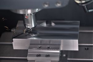
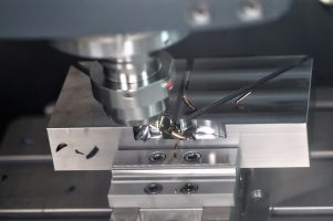
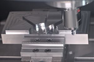
VariMill XTREME超硬ソリッドエンドミルは、切り屑排出の改良とコーナー強度の向上によって強化された汎用性の高い設計を採用することで、工具の破損やたわみを防止し、幅広いワーク材(鋼、ステンレス鋼、鋳鉄、超合金)や加工(ランピング加工、溝加工、プランジ加工、ドリル加工、ヘリカル補間加工、動的ミーリング加工など)において優れた性能を発揮するように設計されています。

特長:

  • 4つの非対称分割フルートと可変ねじれ角により、振動を低減
  • らせん状のエンドフェイスにより、切れ刃とコーナーでの安定性を向上させ、最大のランピング角とヘリカル加工を実現
  • 放物線状のコアにより、工具の安定性を向上させ、たわみと破損リスクを軽減
  • 非線形の深溝プロファイルにより、切り屑排出性を向上させ、ランピング加工とZ軸加工の性能を強化

上記をクリックして拡大/縮小する

VariMill XTREME Cutting

積極性

積極的な切削パラメーターと高度な加工により、期待値を上回る

VariMill XTREME Cutting

生産性

改良された切り屑排出性と向上したコーナー強度により、破損のリスクを軽減

VariMill XTREME Cutting

汎用性

幅広い被削材の加工と加工作業が可能

VariMill XTREMEが製造現場を席巻

この製品設計は、すでに成功を収めているVariMill Iの主な特長を生かしつつ、切り屑排出性とコーナー安定性を向上させることで、幅広い被削材で期待以上の性能を発揮させます。

積極的な切削加工が可能になり、生産性が向上したことで、部品を仕上げるために必要なパス回数を減らすことができます。

VariMill XTREMEは、製造現場を席巻する準備が整っています... 準備できましたか?

VariMill™ XTREME™ 2021
(メトリック版パンフレット)

今すぐ確認する

VariMill XTREME製品を表示

フィルタを選択
フィルタ
フィルタ表示
メートル
インチ
keyFilters
Workpiece Material
Workpiece Material
  • P Steel (139)
    • P0
      Low-Carbon Steels, Long Chipping C < .25%; <125 HB; <530 N/mm^2 UTS (139)
    • P1
      Low-Carbon Steels, Short Chipping C < .25%; <125 HB; <530 N/mm^2 UTS (139)
    • P2
      Medium and High Carbon Steels C < .25%; <220 HB; <25 HRC; >530 N/mm^2 UTS (139)
    • P3
      Alloy Steels & Tool Steels C > .25%; <330 HB; <35 HRC; 600-850 N/mm^2 UTS (139)
    • P4
      Alloy Steels & Tool Steels C > .25%; 350-420 HB; 35-43 HRC; 850-1400 N/mm^2 UTS (139)
    • P5
      Ferritic, Martensitic, and PH Stainless Steels <330 HB; <35 HRC; 600-900 N/mm^2 UTS (139)
    • P6
      High Strength Ferritic, Martensitic, and PH Stainless Steels 350-450 HB; 35-43 HRC; 900-2400 N/mm^2 UTS (139)
  • M Stainless Steel (139)
    • M1
      Austenitic Stainless Steel 130-200 HB; <600 N/mm^2 UTS (139)
    • M2
      High Strength Austenitic Stainless and Cast Stainless Steels 150-230 HB; <25 HRC; >600 N/mm^2 UTS (139)
    • M3
      Duplex Stainless Steel 135-275 HB; <30 HRC; 500-1200 N/mm^2 UTS (139)
  • K Cast Iron (139)
    • K1
      Gray Cast Iron 120-290 HB; <32 HRC; 125-500 N/mm^2 UTS (139)
    • K2
      Low and Medium Strength CGI and Ductile Irons 130-260 HB; <28 HRC; <600 N/mm^2 UTS (139)
    • K3
      High Strength Ductile and Austempered Ductile Iron 180-350 HB; <43 HRC; >600 N/mm^2 UTS (139)
  • S High-Temp Alloys (139)
    • S1
      Iron-Based, Heat-Resistant Alloys 160-260 HB; 25-48 HRC; 500-1200 N/mm^2 UTS (139)
    • S2
      Cobalt-Based, Heat-Resistant Alloys 250-450 HB; 25-48 HRC; 1000-1450 N/mm^2 UTS (139)
    • S3
      Nickel-Based, Heat Resistant Alloys 160-450 HB; <48 HRC; 600-1700 N/mm^2 UTS (139)
    • S4
      Titanium and Titanium Alloys 300-400 HB; 33-43 HRC; 900-1600 N/mm^2 UTS (139)
  • H Hardened Materials (139)
    • H1
      Hardened Materials 44-48 HRC (139)
    • H2
      Hardened Materials 48-55 HRC (139)
Select All Star
  • CN (25)
  • DE (25)
  • GB (10)
  • US (10)
Applications
Applications
  • Pocket Pocket (135)
  • Pocket Helical Pocket Helical (135)
  • Pocket Milling Pocket Milling (135)
  • Pocket Plunge Milling Pocket Plunge Milling (135)
  • Profile Milling Profile Milling (4)
  • Ramping Ramping (135)
  • Shoulder Ball Nose Shoulder Ball Nose (4)
  • Shoulder Milling Shoulder Milling (135)
  • Shoulder Roughing Shoulder Roughing (135)
  • Shoulder Square End Shoulder Square End (82)
  • Slot Ball Nose Slot Ball Nose (4)
  • Slot Milling Slot Milling (135)
  • Slot Square End Slot Square End (135)
  • Trochoidal Milling Trochoidal Milling (139)
Cutting Diameter
Cutting Diameter
  • 0.119 in (1)
  • 0.125 in (4)
  • 0.157 in (5)
  • 0.188 in (5)
  • 0.197 in (5)
  • 0.237 in (6)
  • 0.25 in (5)
  • 0.313 in (8)
  • 0.315 in (7)
  • 0.375 in (5)
  • 0.394 in (7)
  • 0.473 in (7)
  • 0.5 in (26)
  • 0.625 in (3)
  • 0.63 in (7)
  • 0.75 in (23)
  • 0.787 in (6)
  • 0.984 in (2)
  • 1.0 in (7)
Cutting Diameter Min to Cutting Diameter Max
Cutting Diameter
Cutting Diameter
  • 3.0 mm (1)
  • 3.176 mm (4)
  • 4.0 mm (5)
  • 4.775 mm (5)
  • 5.0 mm (5)
  • 6.0 mm (6)
  • 6.351 mm (5)
  • 7.95 mm (8)
  • 8.0 mm (7)
  • 9.525 mm (5)
  • 10.0 mm (7)
  • 12.0 mm (7)
  • 12.701 mm (26)
  • 15.875 mm (3)
  • 16.0 mm (7)
  • 19.05 mm (23)
  • 20.0 mm (6)
  • 25.0 mm (2)
  • 25.401 mm (7)
Cutting Diameter Min to Cutting Diameter Max
Cutting Length
Cutting Length
  • 6.351 mm (2)
  • 7.95 mm (2)
  • 8.0 mm (4)
  • 9.5 mm (1)
  • 9.525 mm (2)
  • 10.0 mm (4)
  • 12.0 mm (6)
  • 12.701 mm (6)
  • 13.0 mm (2)
  • 15.875 mm (6)
  • 16.0 mm (7)
  • 18.0 mm (1)
  • 19.05 mm (6)
  • 20.0 mm (6)
  • 22.0 mm (1)
  • 22.225 mm (3)
  • 24.0 mm (6)
  • 25.401 mm (2)
  • 26.0 mm (1)
  • 31.75 mm (17)
  • 32.0 mm (6)
  • 38.1 mm (14)
  • 40.0 mm (6)
  • 50.0 mm (2)
  • 50.801 mm (10)
  • 57.151 mm (14)
  • 76.2 mm (2)
Cutting Length Min to Cutting Length Max
Cutting Length
Cutting Length
  • 0.25 in (2)
  • 0.313 in (2)
  • 0.315 in (4)
  • 0.374 in (1)
  • 0.375 in (2)
  • 0.394 in (4)
  • 0.473 in (6)
  • 0.5 in (6)
  • 0.512 in (2)
  • 0.625 in (6)
  • 0.63 in (7)
  • 0.709 in (1)
  • 0.75 in (6)
  • 0.787 in (6)
  • 0.866 in (1)
  • 0.875 in (3)
  • 0.946 in (6)
  • 1.0 in (2)
  • 1.024 in (1)
  • 1.25 in (17)
  • 1.26 in (6)
  • 1.5 in (14)
  • 1.575 in (6)
  • 1.969 in (2)
  • 2.0 in (10)
  • 2.25 in (14)
  • 3.0 in (2)
Cutting Length Min to Cutting Length Max
Reach
Reach
  • 0.473 in (3)
  • 0.591 in (3)
  • 0.63 in (1)
  • 0.709 in (5)
  • 0.828 in (1)
  • 0.946 in (5)
  • 1.063 in (1)
  • 1.181 in (5)
  • 1.26 in (1)
  • 1.417 in (6)
  • 1.597 in (7)
  • 1.891 in (6)
  • 2.021 in (8)
  • 2.362 in (6)
  • 2.457 in (7)
  • 2.935 in (7)
Reach Min to Reach Max
Reach
Reach
  • 12.0 mm (3)
  • 15.0 mm (3)
  • 16.0 mm (1)
  • 18.0 mm (5)
  • 21.0 mm (1)
  • 24.0 mm (5)
  • 27.0 mm (1)
  • 30.0 mm (5)
  • 32.0 mm (1)
  • 36.0 mm (6)
  • 40.575 mm (7)
  • 48.0 mm (6)
  • 51.325 mm (8)
  • 60.0 mm (6)
  • 62.401 mm (7)
  • 74.55 mm (7)
Reach Min to Reach Max
Connection Style
Connection Style
  • Straight-Cylindrical (101)
  • Weldon (38)
Over All Length [L]
Over All Length [L]
  • 1.5 in (4)
  • 2.0 in (8)
  • 2.244 in (17)
  • 2.25 in (3)
  • 2.48 in (7)
  • 2.5 in (12)
  • 2.835 in (7)
  • 3.0 in (2)
  • 3.228 in (1)
  • 3.25 in (15)
  • 3.269 in (7)
  • 3.5 in (2)
  • 3.622 in (6)
  • 4.0 in (20)
  • 4.5 in (3)
  • 4.529 in (6)
  • 4.764 in (2)
  • 5.0 in (15)
  • 6.0 in (2)
Over All Length [L] Min to Over All Length [L] Max
Over All Length [L]
Over All Length [L]
  • 38.1 mm (4)
  • 50.801 mm (8)
  • 57.0 mm (17)
  • 57.151 mm (3)
  • 63.0 mm (7)
  • 63.5 mm (12)
  • 72.0 mm (7)
  • 76.2 mm (2)
  • 82.0 mm (1)
  • 82.551 mm (15)
  • 83.0 mm (7)
  • 88.9 mm (2)
  • 92.0 mm (6)
  • 101.601 mm (20)
  • 114.301 mm (3)
  • 115.0 mm (6)
  • 121.0 mm (2)
  • 127.0 mm (15)
  • 152.4 mm (2)
Over All Length [L] Min to Over All Length [L] Max
cornerConfiguration
Corner Style
Corner Style
  • BALL NOSE (4)
  • CHAMFER (15)
  • RADIUS (86)
  • SQUARE END (34)
Corner Radius
Corner Radius
  • 0.0 in (49)
  • 0.008 in (5)
  • 0.012 in (1)
  • 0.015 in (24)
  • 0.02 in (8)
  • 0.03 in (16)
  • 0.039 in (3)
  • 0.06 in (11)
  • 0.079 in (1)
  • 0.09 in (4)
  • 0.119 in (4)
  • 0.12 in (5)
  • 0.157 in (1)
  • 0.19 in (2)
  • 0.197 in (1)
  • 0.25 in (2)
  • 0.375 in (2)
Corner Radius Min to Corner Radius Max
Corner Radius
Corner Radius
  • 0.0 mm (49)
  • 0.2 mm (5)
  • 0.301 mm (1)
  • 0.375 mm (24)
  • 0.5 mm (8)
  • 0.75 mm (16)
  • 1.0 mm (3)
  • 1.5 mm (6)
  • 1.526 mm (5)
  • 2.0 mm (1)
  • 2.275 mm (4)
  • 3.0 mm (4)
  • 3.051 mm (5)
  • 4.0 mm (1)
  • 4.825 mm (2)
  • 5.0 mm (1)
  • 6.351 mm (2)
  • 9.525 mm (2)
Corner Radius Min to Corner Radius Max
Corner Chamfer
Corner Chamfer
  • 0.0 mm (124)
  • 0.1 mm (6)
  • 0.2 mm (4)
  • 0.301 mm (5)
Corner Chamfer Min to Corner Chamfer Max
Corner Chamfer
Corner Chamfer
  • 0.0 in (124)
  • 0.004 in (6)
  • 0.008 in (4)
  • 0.012 in (5)
Corner Chamfer Min to Corner Chamfer Max
application
Maximum Ramp Angle
Maximum Ramp Angle
  • 45.0 (82)
Maximum Ramp Angle Min to Maximum Ramp Angle Max
frontEnd
Neck Diameter
Neck Diameter
  • 0.148 in (4)
  • 0.185 in (4)
  • 0.222 in (5)
  • 0.296 in (6)
  • 0.37 in (6)
  • 0.444 in (6)
  • 0.593 in (6)
  • 0.74 in (6)
Neck Diameter Min to Neck Diameter Max
Neck Diameter
Neck Diameter
  • 3.75 mm (4)
  • 4.7 mm (4)
  • 5.65 mm (5)
  • 7.525 mm (6)
  • 9.4 mm (6)
  • 11.275 mm (6)
  • 15.05 mm (6)
  • 18.8 mm (6)
Neck Diameter Min to Neck Diameter Max
backEnd
Back-End Diameter
Back-End Diameter
  • 3.176 mm (4)
  • 4.775 mm (5)
  • 6.0 mm (17)
  • 6.351 mm (5)
  • 7.95 mm (8)
  • 8.0 mm (7)
  • 9.525 mm (5)
  • 10.0 mm (7)
  • 12.0 mm (7)
  • 12.701 mm (26)
  • 15.875 mm (3)
  • 16.0 mm (7)
  • 19.05 mm (23)
  • 20.0 mm (6)
  • 25.0 mm (2)
  • 25.401 mm (7)
Back-End Diameter Min to Back-End Diameter Max
Back-End Diameter
Back-End Diameter
  • 0.125 in (4)
  • 0.188 in (5)
  • 0.237 in (17)
  • 0.25 in (5)
  • 0.313 in (8)
  • 0.315 in (7)
  • 0.375 in (5)
  • 0.394 in (7)
  • 0.473 in (7)
  • 0.5 in (26)
  • 0.625 in (3)
  • 0.63 in (7)
  • 0.75 in (23)
  • 0.787 in (6)
  • 0.984 in (2)
  • 1.0 in (7)
Back-End Diameter Min to Back-End Diameter Max
No filters matching ""
マイソリューションページにを追加しようとしています. 続行しますか?
product-image
Please adjust the following properties from

ISO製品型番

ANSI製品型番

to find similar products.

The following files are available

Please select a file to download

Models

ダッシュボード情報を表示するには、ログインする必要があります
Session expired due to inactivity, please login again
カートに追加しようとした製品()はありません カスタマーサービスにお問い合わせください。
アイテムがカートに正常に追加されました
カートを表示

. Please enter the desired qty for the material(s) you want to include in your promotion or Proceed Without Promotion and only your base materials will be added to the cart.

Minimum quantity should be

SAP Material Number ISO製品型番 材種    
Thank you for your registration, pending approval & completion of the registration, your access is currently limited. Full utilization of product search capabilities & collaboration space is available and will remain. Please allow 2 business days for registration completion.

You are about to leave the Solution building process.

Are you sure you want to leave?