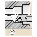
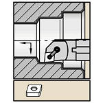
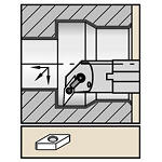
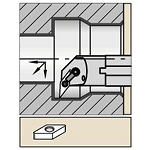
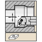
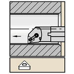
M-Style Clamping • For Negative Style Inserts
-
P Steel (12)
-
P0Low-Carbon Steels, Long Chipping C < .25%; <125 HB; <530 N/mm^2 UTS (12)
-
P1Low-Carbon Steels, Short Chipping C < .25%; <125 HB; <530 N/mm^2 UTS (12)
-
P2Medium and High Carbon Steels C < .25%; <220 HB; <25 HRC; >530 N/mm^2 UTS (12)
-
P3Alloy Steels & Tool Steels C > .25%; <330 HB; <35 HRC; 600-850 N/mm^2 UTS (12)
-
P4Alloy Steels & Tool Steels C > .25%; 350-420 HB; 35-43 HRC; 850-1400 N/mm^2 UTS (12)
-
P5Ferritic, Martensitic, and PH Stainless Steels <330 HB; <35 HRC; 600-900 N/mm^2 UTS (12)
-
P6High Strength Ferritic, Martensitic, and PH Stainless Steels 350-450 HB; 35-43 HRC; 900-2400 N/mm^2 UTS (12)
-
-
M Stainless Steel (12)
-
M1Austenitic Stainless Steel 130-200 HB; <600 N/mm^2 UTS (12)
-
M2High Strength Austenitic Stainless and Cast Stainless Steels 150-230 HB; <25 HRC; >600 N/mm^2 UTS (12)
-
M3Duplex Stainless Steel 135-275 HB; <30 HRC; 500-1200 N/mm^2 UTS (12)
-
-
K Cast Iron (12)
-
K1Gray Cast Iron 120-290 HB; <32 HRC; 125-500 N/mm^2 UTS (12)
-
K2Low and Medium Strength CGI and Ductile Irons 130-260 HB; <28 HRC; <600 N/mm^2 UTS (12)
-
K3High Strength Ductile and Austempered Ductile Iron 180-350 HB; <43 HRC; >600 N/mm^2 UTS (12)
-
-
N Non-Ferrous Materials (12)
-
N1Wrought Aluminum (12)
-
N2Low-Silicon Aluminum Alloys and Magnesium Alloys Si <12.2% (12)
-
N3High-Silicon Aluminum Alloys Si >12.2% (10)
-
N4Copper, Brass, Zinc-based on machinability index range of 70-100 (12)
-
N5Nylon, Plastics, Rubbers, Phenolics, Resins, Fiberglass (10)
-
N6Carbon, Graphite Composites, CFRP (10)
-
N7MMC's (9)
-
-
S High-Temp Alloys (12)
-
S1Iron-Based, Heat-Resistant Alloys 160-260 HB; 25-48 HRC; 500-1200 N/mm^2 UTS (12)
-
S2Cobalt-Based, Heat-Resistant Alloys 250-450 HB; 25-48 HRC; 1000-1450 N/mm^2 UTS (12)
-
S3Nickel-Based, Heat Resistant Alloys 160-450 HB; <48 HRC; 600-1700 N/mm^2 UTS (12)
-
S4Titanium and Titanium Alloys 300-400 HB; 33-43 HRC; 900-1600 N/mm^2 UTS (12)
-
-
H Hardened Materials (11)
-
H1Hardened Materials 44-48 HRC (11)
-
H2Hardened Materials 48-55 HRC (11)
-
H3Hardened Materials 56-60 HRC (10)
-
H4Hardened Materials >60 HRC (10)
-
-
US (2)
-
Facing (1)
-
Multiple Direction Cutting (11)
-
Profiling (10)
-
TRN Boring (12)
-
Turning (1)
-
Heavily Interrupted Cut (12)
-
Lightly Interrupted Cut (12)
-
Smooth Cut (12)
-
90.0 (1)
-
93.0 (4)
-
95.0 (7)
-
1.0 (9)
-
2.0 (7)
-
3.0 (3)
-
4.0 (8)
-
6.0 (4)
-
8.0 (4)
-
7.875 in (1)
-
10.0 in (1)
-
11.811 in (1)
-
12.0 in (1)
-
13.781 in (4)
-
14.0 in (3)
-
16.0 in (1)
-
200.0 mm (1)
-
254.0 mm (1)
-
300.0 mm (1)
-
304.8 mm (1)
-
350.0 mm (4)
-
355.6 mm (3)
-
406.401 mm (1)
-
0.004 in (6)
-
0.008 in (7)
-
0.016 in (10)
-
0.024 in (2)
-
0.031 in (12)
-
0.047 in (12)
-
0.063 in (9)
-
0.095 in (2)
-
0.1 mm (6)
-
0.2 mm (7)
-
0.4 mm (10)
-
0.601 mm (2)
-
0.8 mm (12)
-
1.201 mm (12)
-
1.6 mm (9)
-
2.401 mm (2)
-
CW2015 (9)
-
CW5025 (11)
-
HK1500 (7)
-
PB100 (2)
-
PB170 (2)
-
PB250 (2)
-
PB300 (2)
-
THM (4)
-
THM-X (2)
-
THMF-X (3)
-
TN10P (12)
-
TN10U (9)
-
TN15M (12)
-
TN15U (9)
-
TN2000 (7)
-
TN20K (12)
-
TN20P (12)
-
TN30M (12)
-
TN30P (9)
-
TN4000 (7)
-
TN5015 (9)
-
TN5020 (7)
-
TN5105 (7)
-
TN5120 (9)
-
TN6010 (6)
-
TN6025 (5)
-
TN7005 (6)
-
TN7010 (9)
-
TN7015 (9)
-
TN7025 (9)
-
TN7035 (7)
-
TN7105 (6)
-
TN7110 (9)
-
TN7115 (9)
-
TN7125 (7)
-
TN7135 (7)
-
TN8025 (10)
-
TTI15 (2)
-
TTM09 (1)
-
TTR (2)
-
TTS (4)
-
TTX (3)
-
WBH10C (8)
-
WBH10P (6)
-
WBH10U (9)
-
WBH20P (9)
-
WBH25P (7)
-
WBH25U (5)
-
WBH30P (6)
-
WBK40U (2)
-
WBK45U (5)
-
WDN00U (4)
-
WDN25U (9)
-
WK05CT (12)
-
WK15CT (6)
-
WK20CT (12)
-
WM15CT (12)
-
WM25CT (12)
-
WM35CT (12)
-
WP05CT (4)
-
WP15CT (12)
-
WP25CT (12)
-
WP35CT (12)
-
WS10PT (12)
-
WS25PT (12)
-
WU10HT (12)
-
WU10PT (8)
-
WU25PT (8)
-
L (2)
-
R (10)
-
N (12)
-
Y (7)
-
12.701 mm (1)
-
16.25 mm (1)
-
19.425 mm (1)
-
22.0 mm (1)
-
25.401 mm (1)
-
27.0 mm (1)
-
28.451 mm (1)
-
34.801 mm (1)
-
35.0 mm (4)
-
0.5 in (1)
-
0.64 in (1)
-
0.765 in (1)
-
0.866 in (1)
-
1.0 in (1)
-
1.063 in (1)
-
1.12 in (1)
-
1.37 in (1)
-
1.379 in (4)
-
23.625 mm (1)
-
31.0 mm (1)
-
37.0 mm (1)
-
37.35 mm (1)
-
43.301 mm (1)
-
50.0 mm (1)
-
50.801 mm (1)
-
63.0 mm (4)
-
63.5 mm (1)
-
0.93 in (1)
-
1.22 in (1)
-
1.457 in (1)
-
1.47 in (1)
-
1.705 in (1)
-
1.969 in (1)
-
2.0 in (1)
-
2.48 in (4)
-
2.5 in (1)
-
B (7)
-
E (5)
-
3.0 in (1)
-
3.938 in (1)
-
4.0 in (1)
-
4.992 in (1)
-
5.0 in (1)
-
6.0 in (1)
-
6.299 in (1)
-
7.875 in (4)
-
8.0 in (1)
-
76.2 mm (1)
-
100.0 mm (1)
-
101.601 mm (1)
-
126.801 mm (1)
-
127.0 mm (1)
-
152.4 mm (1)
-
160.0 mm (1)
-
200.0 mm (4)
-
203.201 mm (1)
-
C-DIAMOND/RHOMBIC 80 (4)
-
D-DIAMOND/RHOMBIC 55 (2)
-
T-TRIANGLE 60 (1)
-
V-DIAMOND/RHOMBIC 35 (2)
-
W-TRIGON 80 (3)
-
B H (9)
-
B L (9)
-
C A (9)
-
C N (12)
-
D P (9)
-
H T (2)
-
H W (12)
-
19.05 mm (1)
-
25.0 mm (1)
-
25.401 mm (1)
-
31.701 mm (1)
-
31.75 mm (1)
-
38.1 mm (1)
-
40.0 mm (1)
-
50.0 mm (4)
-
50.801 mm (1)
-
0.75 in (1)
-
0.984 in (1)
-
1.0 in (1)
-
1.248 in (1)
-
1.25 in (1)
-
1.5 in (1)
-
1.575 in (1)
-
1.969 in (4)
-
2.0 in (1)
-
0.939 in (1)
-
1.53 in (1)
-
1.848 in (2)
-
23.826 mm (1)
-
38.825 mm (1)
-
46.95 mm (2)
-
0.864 in (1)
-
1.455 in (1)
-
1.848 in (2)
-
21.951 mm (1)
-
36.95 mm (1)
-
46.95 mm (2)
